Tolerances are everywhere in manufacturing and construction and rightly so. Without them it simply wouldn’t be possible to mass produce the things we take for granted, on anything like the scale we do or at the price we expect to pay.
The Introduction to CWCT Technical Note 21 states:
Lack of understanding of building tolerances is a major source of conflict on site. It increases construction costs and can lead to poor quality buildings or even failures if corrective measures are ill-conceived.
It goes on to explain the difference between Induced and Inherent deviations (the difference between the nominal and actual size) and where in the design process they must be allowed for. It explains that Tolerances define the range of variability allowable within a given design, and that it may be expressed with equal deviation around the nominal value as in ± x or as an + x, – y, maximum to minimum size.
Accuracy, or reduction of deviation is relative and should be applied appropriately to the conditions and requirements of the situation. In cladding and facades, we work to installation tolerances typically around ± 2mm but we must fix to a building frame with tolerances which may be typically ± 15mm or more. While it may be desirable form the cladding contractor’s perspective to have the concrete installed to the same level of accuracy as the cladding, this is never going to happen and so we need to deal with it in design.
Dealing with induced tolerances in design is straightforward with understanding of the materials and manufacturing constraints involved. Indeed, the tolerances are laid down in normative standards for most of the materials we use, and we simply need to understand these and design our fabrication or assembly such that the combination of parts and materials fit together properly, and act in concert when under their own or environmental inherent deviations.
By far the biggest impact on any façade design is movement. We need to accommodate movement resulting from deflection of the cladding under wind load obviously, but we must also deal with the fact that the building frame will move around behind the cladding under the influence of live loads including occupancy and natural shrinkage or creep of the materials used to construct it and, in some areas, significant seismic movement. Movement also happens within the façade because of thermal expansion and contraction and is much more significant a factor than one would think at first.
Aluminium has a coefficient of linear thermal expansion of 0.000023m/m°C which doesn’t sound exciting in the least with all those zeros, but what it means is that aluminium will expand 1mm per linear meter in length over a temperature range of 40°C. Again, not terribly interesting but a mullion spanning 3500mm from floor slab to floor slab will want to expand by 3.5mm. This must be respected and allowed to happen using sliding connections as preventing it by pinning both ends will lead to unacceptable levels of stress in the member and possibly permanent deformation and glass breakage. In panels this deformation is seen in the form of “oil canning” or “quilting” of flat surfaces. To understand this and put 0.000023 m/m°C into context what it means is that if you take a 1000mm² aluminium panel and restrict all 4 edges to prevent the panel growing to 1001 x 1001mm when under a 40°C temperature change the result will be the centre will distort by 16mm and the 3500mm long mullion will want to distort by 68mm if pinned.
In unitised curtain walls this movement and tolerance is taken up in the stack joint – the split transom where panels connect generally at slab levels. It is the most significant factor in determining the size of the joint because when designing or selecting the system, one needs to consider the total movement deviation under live load which could easily be ± 8mm, thermal expansion of +1mm per linear meter, fabrication tolerance of ±1mm and installation tolerance of ±2mm. Allow another say 3mm for gasket compression as they cannot compress to zero and one starts to understand that the stack joint seen on the elevation, as a nominal 20mm wide could theoretically range from 5 to 35mm and that the engagement of the split transoms must accommodate this without bottoming out or losing structural integrity or weather and air tightness in the gasket system.
Figure 1:
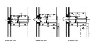
Units in a unitised wall are engineered without internal movement joints, with horizontal movement allowances specifically designed at the top and bottom joints of each unit. Figure 1 above shows a typical stack joint with a 20mm nominal joint size and a nominal ±13mm movement allowance. It can be seen from this that the joint cannot close to accommodate more movement nor can it reasonably open more without compromising the structural engagement or the weather and air tightness.
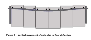
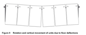
Furthermore, the unitised elements will be structured to adapt to occupancy loads, effectively mirroring or adjusting to the floor deflection of the underlying structure as needed. See Figure 8 & 9.
The following CWCT Technical notes give much more detail and explanation of the factors and effects of movement and tolerance in a façade or cladding system;
TN 55 Movement accommodation in building envelopes
TN 56 Accommodation of structural movement
TN 57 Cladding movement
While it may be argued that the mullions themselves are in an ambient zone on the warm side of a thermally broken system, we are required to design to codes and specifications and no dispensation is given or implied to differentiate between the internal and external parts of a system.
With reference to the CWCT ‘Standard for Systemised Building Envelopes’ Part 2 Section 2.7.2; the surface temperatures shall be as follows:
Heavyweight materials
light colour -20°C to +50°C
dark colour -20°C to +65°C
Lightweight insulated materials
light colour -25°C to +60°C
dark colour -25°C to +80°C
Glass
clear -25°C to +40°C
The structural engineer when designing the building frame must be made aware of and make provision for the architectural aspiration in respect of the façade, and how joints are expressed, and movement accommodated. If the frame is not designed with the façade in mind, it is possible that the façade supplier will not be able to deliver what the architect wants if the intent is for smooth glass wall with minimal jointing and crisp lines without the addition of expensive secondary steelwork such as trusses spanning between columns to hang panels or glazing from. All of this demonstrates once again the need for a holistic approach to building design and early engagement of façade engineers or specialist façade contractors.


